EMBEDDED
C TUTORIAL
TIMOTHY ADEGBITE
Welcome to today’s Trinnex electronics tutorial on
Embedded C. hope you have been enjoying the tutorial. Remember, this is a place for startups in
electronics and embedded system programmers. If you think you are not a startup
and you need more advance tutorial, you can send me a mail or chat with me, I
will gladly reply you.
I decided to post this tutorial earlier than the
time stipulated. My schedules seems to be less tight, so I decided to use it in
posting this tutorial.
Today, we will be working on a LED chaser, the
simple one. You will frequently see this in Christmas lights. It tends to
create a sensation of LEDs running after each other. The faster it is, the more
obvious the sensation will be. You can design any form of LED chaser. It all
depends on your creativity.
In this project, we will be using the whole 8
ports of PORTB of the microcontroller.
Below shows the code written to achieve this.
//This is a simple project, demonstrating how to design
//an LED chaser.
#include < xc.h > // header file that includes
//all
the files in the pic16f84a
#define _XTAL_FREQ 4000000 // clocking frequency is 4Mhz
void main(void) // This is the main function.it receives no
//argument and returns no value.
// it is a void
function.
{
TRISA=0B00000000; //
equates all PORTA as an output port
TRISB=0B00000000; //
equates all PORTB as an output port
PORTA=0; //
clears PORTA bits
PORTB=0; // clears PORTB bits
while(1) // While loop; it iterates continuously
{
PORTBbits.RB7 =0; // clear bit 7 of PORTB
PORTBbits.RB0 =1; // Set bit 0 of PORTB
__delay_ms(100); // delay for (100ms)
PORTBbits.RB0 =0; // clear bit 0 of PORTB
PORTBbits.RB1 =1; // set bit 1 of PORTB
__delay_ms(100); // delay for (100ms)
PORTBbits.RB1 =0; // clear bit 1 of PORTB
PORTBbits.RB2 =1; // Set bit 2 of PORTB
__delay_ms(100); // delay for (100ms)
PORTBbits.RB2 =0; // clear bit 2 of PORTB
PORTBbits.RB3 =1; // Set bit 3 of PORTB
__delay_ms(100); // delay for (100ms)
PORTBbits.RB3 =0; // clear bit 3 of PORTB
PORTBbits.RB4 =1; // Set bit 4 of PORTB
__delay_ms(100); // delay for (100ms)
PORTBbits.RB4 =0; // clear bit 4 of PORTB
PORTBbits.RB5 =1; // Set bit 5 of PORTB
__delay_ms(100); // delay for (100ms)
PORTBbits.RB5 =0; // clear bit 5 of PORTB
PORTBbits.RB6 =1; // Set bit 6 of PORTB
__delay_ms(100); // delay for (100ms)
PORTBbits.RB6 =0; // clear bit 6 of PORTB
PORTBbits.RB7 =1; // Set bit 7 of PORTB
__delay_ms(100); // delay for (100ms)
}
}
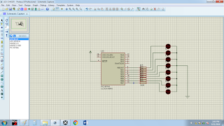
After compiling and running it on proteus, you see
the LED chasing each other.
In the next tutorial, I will explain how to use the ports
of the microcontroller as an input PORT, but before then, I have a little task.
ASSIGNMENT:
In the video below, you will see that the LEDs are chasing
downward. Design yours, making it chase upward, post your codes here, to
see how efficient your code is and I will give my comment on how it can be
improved on,next week tuesday. Remember, there is not short cut to knowing this than constant
practice!!!
Below shows the finished prototype of
the design on Proteus.the simulation has a bit of delay. This is due to the recording software I used.
You can always post your comments here, for further
clarifications and questions.

Comments